This circuit is used to trigger a relay with a 12 V the touch of the hand. He uses the ability of
conduction of the skin. Once again the master of the house is the indestructible NE555 timer; in this circuit is mounted conventionally monostable configuration.
Attach it to the handle of the door and that it protects the entrance to your studio, your bedroom or even your secret drawer. When he touches the handle, the key lock ... the intruder receives the ringing of the alarm siren in the ears (controlled by relay) and prefers to slip: 90 dB of a mermaid that makes very sore eardrums and then think it will round up the world! This type of connection is also perfect to surprise
the guest at a party in his honor when he touches the handle, a light string lights and, why not, a welcome message, good party ... is reproduced! But you can also use it to start with a simple touch of the hand, a pre recorded message. Or to protect against the fridge kind of nocturnal predators (no, not necessarily children ...) as soon as the nocturnal visitor touches the handle opening, a small alarm (more discreet than for real thieves) sounds, and
puts in trouble, facing his vice bulimic! But stop there the enumeration of these applications suggestions because we are certain that you will find many others.
 The wiring diagram:
To operate the circuit, Figure 1 shows the circuit diagram, a 9V battery is sufficient (but a 12 V - car battery or 230 V - both will do). The NE555 was mounted in monostable configuration: its output pin 3 remains in the condition it is in the power until the voltage on pin 2 (normally it is that of food) goes down below 1/3 of the supply voltage.
The timer begins for a given time T by the formula:
T = 1.1 x R2 x C2
The voltage on pin 2 goes down when we touch with hand the wire connected to the trimmer R1: this action
determines a connection to the earth through our body. The capacitor C1 initially charged by the supply voltage, discharges through R1, in series with the resistance of the body, towards the earth and the voltage on pin 2 drops to 0 V.
The consequence is that a voltage pulse is formed on pin 3, for a time T that impulse drives the base of the transistor TR1 becomes conductive and supplies the winding of the relay. In parallel with this coil we set up an LED DL1, without forgetting its R5 current limiting resistance, too, when the relay glue, the LED lights.
The DS1 LED is connected in parallel with the relay coil, but it is as celleci protection against surges. Indeed, in a solenoid, whenever a voltage change occurs, a sign inverse electromotive force takes place and without the diode which cancels, wherein the transistor is damaged it will discharge.

The practical realization:
First realize (Method of blue film) from the scale drawing 1: 1 in Figure 2b the single sided printed circuit or get it. When you're looking at, first press (with a small hammer and by relying on a metal plate drilled a hole) the stud welding going trigger wire to the touch. Insert the media also 2 x 4 pins of the integrated circuit, but insert it at the end. Then insert all components, you then solder on. Start Up
by inserting the five resistors, capacitors and two polyesters two electrolytic capacitors carefully observing the polarity of these: the - sign is screen printed multiple times
along the corresponding housing of the "leg" negative. The - C1 and C3
go to the ground strip which forms an L on the left side of the circuit. Continue inserting the transistor
TR1, benchmark-keyed (pin its metal housing) oriented in the right direction: towards mass L. track Solder the LEDs in the AK holes (in the relay), taking care that the polarity:
the anode A into hole A and cathode K in the K hole; knowing that the longest leg of an LED is the anode. If you think you should deport this LED for your personal application, extend its legs with plastic-coated copper wire: black for the cathode K - and red for anode A +. The flat surface of the transparent housing of the LED corresponds to the cathode K, as shown in Figure 2a, but it is difficult to see. Insert the two trimmers and over and finally the two terminals. Flip the board and solder all the pins and tails all components carefully. Also solder the pin. Cut the remaining lengths. Make sure the welds (shiny, without short circuit between tracks or pads or cold solder joints) before inserting the NE555 in its holder, landmark-keyed U oriented C4.
Component side, now screw the two son going to 12V (or
in decision-9V) in the bottom terminal, red + left and the black - right. Into the terminal screw top three son, connected to the relay outputs, they are used to control the load (the siren for the applications we considered at the beginning of the article). For all this use 2a and
3 but also the wiring diagram in Figure 1 and the list of associated components. So you will not go wrong. These tips are for beginners, since the purpose of this triptych is primarily didactic.

List of components:
R1 ...... 1M trimmer
R2 ...... 220 k trimmer
R3 10k ......
R4 ...... 1k
R5 ...... 1k
C1 ...... 10 uF electrolytic
C2 ...... 4.7 nF polyester
C3 ...... 100 uF electrolytic
...... C4 100 nF polyester
DS1 ... 1N4007
DL1 LED ....
TR1 .... NPN 2N2222A
IC1 NE555 .....
RL1 .... 12V relay 1 contact
Other:
1 3-pin terminal block
1 2-pin terminal block
Note: resistors are quarter-W.
The setting of trimmers:
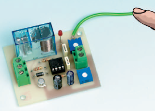
Turn their axes far left (counterclockwise) and far right (clockwise) and then adjust them mid Feed the race circuit with a 9V battery or 12V (battery or power adapter small constant) .dropoff window As long as you do not touch the TEST wire (yellow Figure 2a), nothing happens; from
you touch it, the relay trips and LED lights. After some time, precisely adjustable with the trimmer R2 TIME, the relay turns off. R1 SENSITIVITY trimmer serves him to adjust the trigger touch sensitivity of the circuit. If you find that from time to time the relay trips without reason, act on the axis of R1 to stabilize the relay.
conduction of the skin. Once again the master of the house is the indestructible NE555 timer; in this circuit is mounted conventionally monostable configuration.
Attach it to the handle of the door and that it protects the entrance to your studio, your bedroom or even your secret drawer. When he touches the handle, the key lock ... the intruder receives the ringing of the alarm siren in the ears (controlled by relay) and prefers to slip: 90 dB of a mermaid that makes very sore eardrums and then think it will round up the world! This type of connection is also perfect to surprise
the guest at a party in his honor when he touches the handle, a light string lights and, why not, a welcome message, good party ... is reproduced! But you can also use it to start with a simple touch of the hand, a pre recorded message. Or to protect against the fridge kind of nocturnal predators (no, not necessarily children ...) as soon as the nocturnal visitor touches the handle opening, a small alarm (more discreet than for real thieves) sounds, and
puts in trouble, facing his vice bulimic! But stop there the enumeration of these applications suggestions because we are certain that you will find many others.
To operate the circuit, Figure 1 shows the circuit diagram, a 9V battery is sufficient (but a 12 V - car battery or 230 V - both will do). The NE555 was mounted in monostable configuration: its output pin 3 remains in the condition it is in the power until the voltage on pin 2 (normally it is that of food) goes down below 1/3 of the supply voltage.
The timer begins for a given time T by the formula:
T = 1.1 x R2 x C2
The voltage on pin 2 goes down when we touch with hand the wire connected to the trimmer R1: this action
determines a connection to the earth through our body. The capacitor C1 initially charged by the supply voltage, discharges through R1, in series with the resistance of the body, towards the earth and the voltage on pin 2 drops to 0 V.
The consequence is that a voltage pulse is formed on pin 3, for a time T that impulse drives the base of the transistor TR1 becomes conductive and supplies the winding of the relay. In parallel with this coil we set up an LED DL1, without forgetting its R5 current limiting resistance, too, when the relay glue, the LED lights.
The DS1 LED is connected in parallel with the relay coil, but it is as celleci protection against surges. Indeed, in a solenoid, whenever a voltage change occurs, a sign inverse electromotive force takes place and without the diode which cancels, wherein the transistor is damaged it will discharge.
The practical realization:
First realize (Method of blue film) from the scale drawing 1: 1 in Figure 2b the single sided printed circuit or get it. When you're looking at, first press (with a small hammer and by relying on a metal plate drilled a hole) the stud welding going trigger wire to the touch. Insert the media also 2 x 4 pins of the integrated circuit, but insert it at the end. Then insert all components, you then solder on. Start Up
by inserting the five resistors, capacitors and two polyesters two electrolytic capacitors carefully observing the polarity of these: the - sign is screen printed multiple times
along the corresponding housing of the "leg" negative. The - C1 and C3
go to the ground strip which forms an L on the left side of the circuit. Continue inserting the transistor
TR1, benchmark-keyed (pin its metal housing) oriented in the right direction: towards mass L. track Solder the LEDs in the AK holes (in the relay), taking care that the polarity:
the anode A into hole A and cathode K in the K hole; knowing that the longest leg of an LED is the anode. If you think you should deport this LED for your personal application, extend its legs with plastic-coated copper wire: black for the cathode K - and red for anode A +. The flat surface of the transparent housing of the LED corresponds to the cathode K, as shown in Figure 2a, but it is difficult to see. Insert the two trimmers and over and finally the two terminals. Flip the board and solder all the pins and tails all components carefully. Also solder the pin. Cut the remaining lengths. Make sure the welds (shiny, without short circuit between tracks or pads or cold solder joints) before inserting the NE555 in its holder, landmark-keyed U oriented C4.
Component side, now screw the two son going to 12V (or
in decision-9V) in the bottom terminal, red + left and the black - right. Into the terminal screw top three son, connected to the relay outputs, they are used to control the load (the siren for the applications we considered at the beginning of the article). For all this use 2a and
3 but also the wiring diagram in Figure 1 and the list of associated components. So you will not go wrong. These tips are for beginners, since the purpose of this triptych is primarily didactic.
List of components:
R1 ...... 1M trimmer
R2 ...... 220 k trimmer
R3 10k ......
R4 ...... 1k
R5 ...... 1k
C1 ...... 10 uF electrolytic
C2 ...... 4.7 nF polyester
C3 ...... 100 uF electrolytic
...... C4 100 nF polyester
DS1 ... 1N4007
DL1 LED ....
TR1 .... NPN 2N2222A
IC1 NE555 .....
RL1 .... 12V relay 1 contact
Other:
1 3-pin terminal block
1 2-pin terminal block
Note: resistors are quarter-W.
The setting of trimmers:
Turn their axes far left (counterclockwise) and far right (clockwise) and then adjust them mid Feed the race circuit with a 9V battery or 12V (battery or power adapter small constant) .dropoff window As long as you do not touch the TEST wire (yellow Figure 2a), nothing happens; from
you touch it, the relay trips and LED lights. After some time, precisely adjustable with the trimmer R2 TIME, the relay turns off. R1 SENSITIVITY trimmer serves him to adjust the trigger touch sensitivity of the circuit. If you find that from time to time the relay trips without reason, act on the axis of R1 to stabilize the relay.


