
In this article, we guide you through the construction of the Car Scrolling Display.
We also show you how to install the software driver that’s used to communicate with the display via a USB port on a Windows PC.
All the parts for the Car scrolling Display are installed on two pc boards – a main board coded 786 (134 × 86mm) and a display board coded 787 (124 × 75mm). These two boards are stacked together with a red Perspex window and are secured using nylon spacers, washers and screws.
Note that there is no wiring between the two boards. The display board simply plugs into the main board via connector CON6.
Note also that the display board is smaller than the main board. That’s been done so that when the two boards are stacked together, the screw terminal blocks on the main board are exposed for easy access.
Main board assembly
Fig.6 shows the assembly details for the main board. Begin by checking the board for cracks in the tracks or any shorts between adjacent tracks.
This is easier to do before installing the parts and can save you trouble later.
Once you are convinced that the pC board is OK, start the assembly by soldering in the 10 wire links. You must do this first, as two of these links (lK5 and lK6) are underneath the 40-pin IC socket.


These links should be installed sing tinned copper wire. You can straighten this link wire by first clamping one end in a vice and then pulling the other end with pliers to stretch the wire slightly. After that, it’s simply matter of cutting the links to length and using pliers to bend their leads own at right angles so that they fit the PC board.
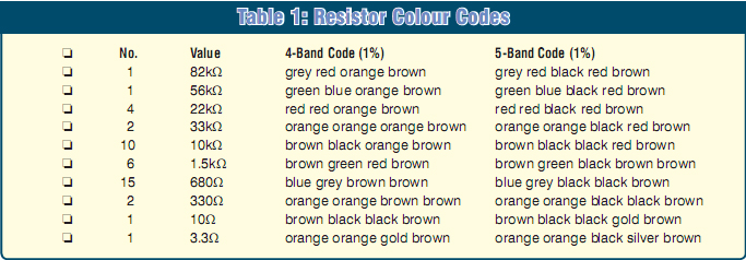
There are 24 resistors on the main C board, and they can be soldered in next. You must make sure that the correct value is used at each location. The color code table shows how to decipher the values, but it is also prudent to check each one with a multimeter before it is soldered in place. Note that the 10Ω resistor must be rated at 1W.
Once the resistors are in, the diodes can be installed. There are eight diodes in total, of four different types.
Begin by installing 16V Zener diode ZD1. Refer to the component overlay for its location and orientation! Remember that the cathode of a diode is normally indicated by a stripe.
The signal diode (D7, a 1N4148) is used for ICSP (in-circuit serial programming) and is installed near CON5 (the ICSP header). You only really need it if you intend to program the microcontroller (IC1) in circuit; otherwise it can be left out.
Diodes D5 and D6 are next on the list. Note that these were shown as 1 N 5 8 1 9 Schottky types on the circuit diagram (Fig.3) last month, but in practice, 1N4004 diodes will do, and that’s what are now specified in the parts list. Be sure to install them with the correct orientation.
By contrast, diode D4 must be a 1N5819 Schottky type (as originally specified). This can now be installed, followed by the five remaining diodes, which are all 1N4004s.
The four transistors can now all go in. These are all BC337 NPN types and each must be correctly oriented, as shown in Fig.6.
Now for the capacitors. The ceramic and the 100nF monolithic capacitors are not polarized and can go in either way around. However, the electrolytic capacitors are polarized, so be sure to install them as indicated on the overlay.
Note particularly that all the electrolytic capacitors must have their leads bent by 90° so that their bodies lie horizontally on the PC board – see photo.
Do not mount them vertically; if you do, they will interfere with the bottom of the display board when the boards are stacked together.


Once you’ve installed the capacitors, you are ready to install the connectors and the IC socket. Install the 40-pin IC socket first, making sure that it is oriented correctly with its notched end as indicated. Note that the IC is not installed in the socket just yet. That step comes later, after some preliminary checks of the supply rail.
Install the right-angled 6-pin ICSP header (CON5) only if you intend to program the microcontroller. Note that you will need to cut away the plastic locating guide on this connector if you intend to use the PicKit2 programmer from Microchip. In addition, CON5 should be mounted about 2mm above the PC board in order to ft the PicKit2 programmer.
The rest of the connectors are screw terminal blocks CON1 to CON4. These consist of 2-terminal and 3-terminal blocks, which are combined by sliding their dovetailed ends together.
As shown, CON1 and CON4 are each made by sliding two 2-terminal connectors together, while CON3 consists of two 3-terminal connectors. CON2 is a single 3-terminal connector.
Making up CON6
CON6, a 27-way connector is made by frst cutting a 40-pin IC socket into two 20-pin sockets. You can use a small fne-toothed hacksaw to do this job.
As shown on Fig.6, CON6 is split into three parts. The first is a 14-pin connector; the second is a 5-pin connector and the last is a 7-pin connector (note: pin 15 is not used). You make these by first cutting one 20-pin connector into 14-pin and 5-pin connectors. The 7-pin connector is then cut from the remaining 20-pin connector.
Regulator REG1 can go in next. As shown, this device is mounted horizontally with its leads bent down by 90°, to go through their matching PC board holes. In addition, the regulator must be fitted with a small U-shaped finned heatsink, and this is sandwiched between the regulator’s tab and the PC board.

Secure this assembly to the PC board using an M3 × 10mm screw, lockwasher and nut before soldering the regulator’s leads. If you solder the leads first, the soldered joints may crack as the mounting screw is tightened down.
Note that we specified an LM-2940CT-5 low drop-out regulator in the schematic (Fig.3), you can also use a common (and much cheaper) 7805 regulator in its place, if you wish.
The only drawback here is that using the 7805 means that you will have to power the circuit from a 12V supply. By contrast, the LM2940CT-5 will work with supply voltages down to as low as 9V.
The LM2940CT-5 also contains in-built reverse polarity protection, but we don’t use it in this circuit. That’s because reverse polarity protection is provided by diode D1.
Construction of the main PC board can now be completed by installing the 20MHz crystal. It’s non- polarized, so it can go in either way around.
Display board assembly
Fig.7 shows the parts layout on the display board. Begin the assembly by installing the 21 wire links (LK1 to LK21). Some of these links are quite long and run close together, so it’s important that they are straight before they are installed (stretch the link wire to straighten it).
The resistors can go in next. Note that the 3.3Ω resistor must be rated at 0.5W, while the others are all rated at 0.25W.
Now solder in the two 16-pin IC sockets. These must be oriented with their notched ends as shown on Fig.7.
Note that although these sockets are optional, we do recommend them.
They make it much easier to replace the ICs, if necessary.
The next step is to install six 7-pins socket strips to accept the dot-matrix LED arrays. These are made by cutting three 14-pin IC sockets in half and then cleaning up the edges using a small file. That done, the sockets strips can be soldered in place.
These sockets are used simply to space the LED arrays off the board, so that they later sit close to the red
Perspex front panel. They also make it easier to replace a module in the unlikely event that it fails.
You can now install the two ICs in their sockets, making sure they are correctly oriented. Don’t get these two ICs mixed up – IC2 is the 74HC595 shift register, while IC3 is the ULN2003 Darlington array.
The three LED modules can also be installed in their sockets, each with pin 1 at bottom left. Pin 1 of each module is indicated by a digit on the side.
Once this is done, you can solder in the 15 BC327 transistors. Be sure to orient them as shown and push them down onto the board as far as they will comfortably go before soldering their leads.
Next, solder the two capacitors in place. The 100nF monolithic type is not polarized, but the 470μF electrolytic is, so take care when installing it.
The three pin connector strips that make up CON7 can now be installed.
These are made from a 32-way strip that’s cut into three pieces of 14, 7 and 5 pins. As shown in the photo, these are installed from the component side of the PC board.
Now install the USB type B socket. It sits vertically on the PC board and only fits one way around. Its two tabs can be bent fat against the underside of the board to secure it in position before soldering. Solder its four pins and both tabs to the PC board.
The last thing to do is to solder in the LDR. This should be installed about 10mm above the PC board, so that it later sits just below the front panel.
That completes the assembly of the two PC boards. The next step is to make the front panel.

Fig.8: follow this drilling and cutting diagram to make the front panel. It’s made from 3mm-thick red Perspex measuring 124mm × 75mm.
Preparing the front panel
The front panel is made from a single piece of red Perspex measuring 124 × 75mm (ie, the same dimensions as the display board). Fig.8 shows the cutting and drilling details. There are four 3mm-diameter holes for securing it to the display board, plus a larger (13mm) hole for pushbutton switch S1.
In addition, you need to make a square cut-out to provide access to the USB socket.
Once you’ve cut and drilled the panel, fit the pushbutton switch in place and wire it back to the display board using two 60mm lengths of hook-up wire. The front panel is then fitted with four M3 × 12mm tapped nylon spacers, plus four nylon washers which are secured using M3 × 25mm nylon screws – see Fig.9.
The display board can now be fitted in position over the nylon screws.
Another four nylon washers are then fitted, after which another four M3 × 12mm nylon spacers are wound on.


Preliminary tests
Before attaching the main board, it’s a good idea to carry out a power supply check to confirm that the +5V supply rail is correct. Note that this should be done with microcontroller IC1 OUT of its socket.
First, connect a 12V battery to the power input terminals of CON1 (pin 4 is the +12V input, pins 2 and 3 are ground). Apply power and check the voltage at pin 1 of CON3. If it’s close to +5V, then everything is in order. Note that this voltage can normallyrange from 4.9V to 5.1V. A voltage above 6V or lower than 4.5V indicates that there is a problem and you should disconnect power immediately.
Assuming that the +5V rail measures. OK, you can now disconnect power and install IC1 in its socket. Note that this IC must be programmed with the firmware hex file. If you are building this project from a kit, it will be supplied preprogrammed.
Final assembly
Having checked that the +5V rail is. OK, it’s time to complete the assembly.
This simply involves plugging the display board into the main board and then securing the assembly using four M3 × 6mm nylon screws.

Switch on
Once the assembly has been completed, apply power (ie, via CON1).
You should now see a message scroll past on the LED display modules.
Among other things, this default welcome message should show the firmware version.
If you see this, then everything is working correctly and you can proceed to the next section, which explains how to install the software driver on your PC. If not, you should refer to the troubleshooting panel.
Driver installation
The USB device interface for the Car Scrolling Display uses the generic Microchip driver for Windows. Before communicating with the display using the PC host program, you will need to install this driver. This section explains how to install the driver in
Windows XP, although other versions of Windows will be similar.
The first step is to download the Microchip installer (MCHPFSUSB_Setup_v1.3.exe) from the EPE website and run it. Note that you should use version 1.3, as older or newer versions may not be compatible. The installer program will typically put the driver in the C:\MCHPFUSB\Pc\MCHPUSBDriver\Release folder.
Next, connect the Car Scrolling Display to your computer using a USB cable. Windows will recognize the device as a ‘Display’ and then the ‘Found New Hardware’ Window will appear as shown in Fig.10. Select the ‘No, not this time’ option and click ‘Next’. You will now be presented with a new dialog window. Select ‘Install from a list or specific location’ and click ‘Next’ again to bring up the dialog shown in Fig.11. Select ‘Search for the best driver in these locations’ and enable the ‘Include this location in the search’ box.
Now click the ‘Browse’ button. In the ‘Locate File’ window that appears, navigate to where the MCHPUSB files were installed (normally C:\MCHPFUSB\Pc\MCHPUSB Driver\Release) and select ‘mchpusb.inf’.
Click ‘Next’ and Windows will then install the driver.
If the driver is installed correctly, the ‘Microchip Custom USB Device’ entry should now be visible if you go into Device Manager (Control Panel >System ¬> Hardware tab ¬> Device Manager Button) – see Fig.12 (provided the device is connected).


Using the host software
Once the driver has been installed successfully, you control the Car Scrolling Display using the PC host program cardisplay.exe. This program allows you to change all settings and to do data logging. It is also used for calibration.
Once you’ve connected the Car Scrolling Display’s inputs to the sensors you are interested in monitoring, you can then use a laptop in your car to perform the calibration (you only have to do this once) or change any other system settings (such as the display brightness).
You can also use a laptop in your car to do real time data logging of the signals. Of course, you will need someone else to do the driving while you do this!
To install the PC host program, you first have to download the compressed file ‘cardisplay.zip’ from the EPE web-site (www.epemag.com). You’ll find it in the downloads library section.
Extract the files in the zipped archive to a folder on your hard drive.
There should be at least two files:
1) cardisplay.exe – this is the executable command line program
2) cardisplay.map – this file is used internally by the host program. It must be in the same folder as cardisplay.
exe for the program to recognize it.
Note that the map file is produced by the C compiler of the firmware. It contains memory mapping information for the firmware produced by the linker. When and if the firmware is updated, the map file will also change and this new file must be copied to the folder containing cardisplay.exe in order for it to work correctly.
So, installing the PC host program is easy – just copy the cardisplay.exe and cardisplay.map files to your chosen folder. Once that’s done, you simply go to a command prompt to run the program using your chosen command line option.